Fig. 10.1 shows a simplified circuit diagram for an electric oven. The oven contains a fan driven by a motor.
(a)On Fig. 10.1, circle the symbol representing the heater.
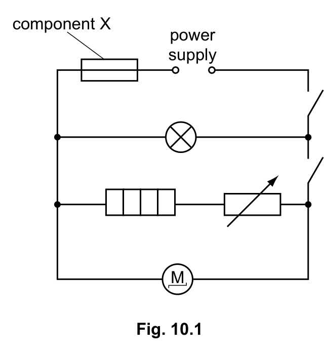
Fig. 10.1 shows a simplified circuit diagram for an electric oven. The oven contains a fan driven by a motor.
(a)On Fig. 10.1, circle the symbol representing the heater.
Fig. 10.1 shows a simplified circuit diagram for an electric oven containing a lamp, a heating element in series with a variable resistor, and a fan motor, all in parallel across the power supply. Fig. 10.1 includes a variable resistor.
(b)Explain the function of the variable resistor in this circuit.
An electric oven contains a fan driven by a motor. The potential difference across the motor is 250 V. The current in the motor is 2.0 A.
(c)Calculate the resistance of the motor.
0625/03/SP/23Cambridge IGCSE Physics 0625 · Specimen 2023 · Paper 3 · Question 10